
A leaking A/C hose after a fresh crimp is one of the most frustrating problems in any workshop. You did the work, but the system still fails. The root cause is almost never the machine.
Proper A/C hose crimping comes down to three things: matching the correct die to the fitting model, verifying insertion depth before the crimp, and running both a dimensional check and a pressure test after. Skip any one of these, and the joint will likely fail under operating pressure.
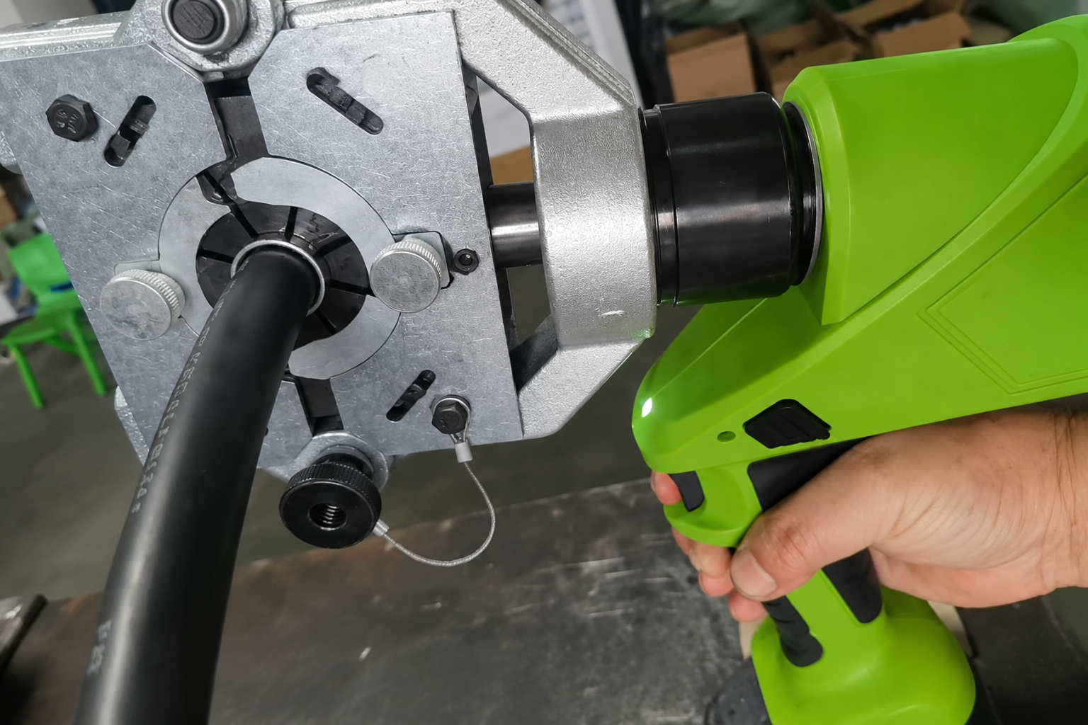
I have been on the factory floor and on calls with technicians from workshops across dozens of countries. The same failure pattern shows up every time. It is not a skill problem. It is a matching and setup problem. The rest of this article will walk you through each decision point so you can stop the leak before the crimp ever happens.
Why Does Proper Crimping Matter?
A bad crimp does not always fail immediately. That is the problem.
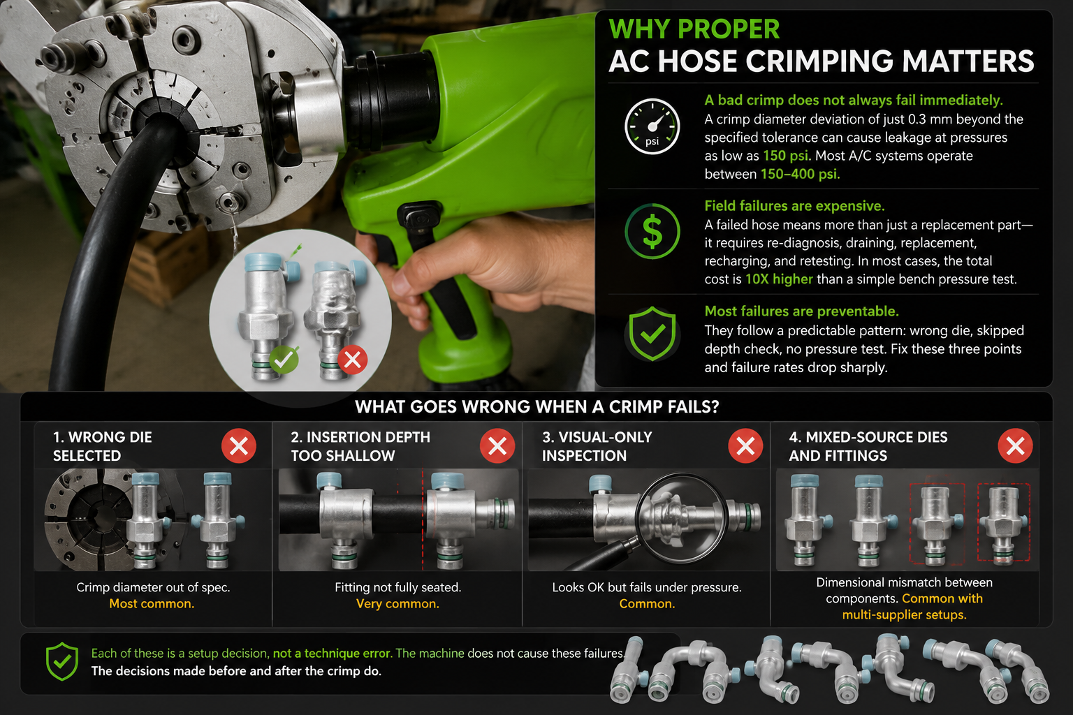
A crimp that looks fine visually can still leak at operating pressure. In our factory testing, a crimp diameter deviation of just 0.3 mm beyond the specified tolerance causes leakage at pressures as low as 150 psi1. Most automotive A/C systems operate between 150 and 400 psi depending on the refrigerant and load condition2.
That gap between "looks okay" and "holds pressure" is where most field returns come from.
When a hose fails in the field, the cost is not just the replacement part. The technician has to redo the diagnosis, drain the refrigerant, replace the hose, recharge the system, and test again. From our post-sale communication with workshop customers, a field failure typically costs ten times more in labor and materials than a simple bench pressure test would have cost at the time of assembly3.
The good news is that most crimping failures are fully preventable. They follow a predictable pattern: wrong die, skipped depth check, no pressure test. Fix those three points and the failure rate drops sharply.
What Goes Wrong When a Crimp Fails?
| Failure Cause | What Happens | How Often We See It |
|---|---|---|
| Wrong die selected | Crimp diameter out of spec | Most common |
| Insertion depth too shallow | Fitting not fully seated | Very common |
| Visual-only inspection | Pressure failure found in the field | Common |
| Mixed-source dies and fittings | Dimensional mismatch between components | Common with multi-supplier setups |
Each of these is a setup decision, not a technique error. The machine does not cause these failures. The decisions made before and after the crimp do.
What Equipment Do You Need?
Not every crimping machine is the same, and treating them as interchangeable is a mistake.
You need a hydraulic or electric crimping machine matched to your hose size range, a complete set of dies that correspond to your fitting models, a depth gauge or marking tool, a vernier caliper for post-crimp diameter measurement, and a pressure testing setup capable of reaching at least 500 psi.
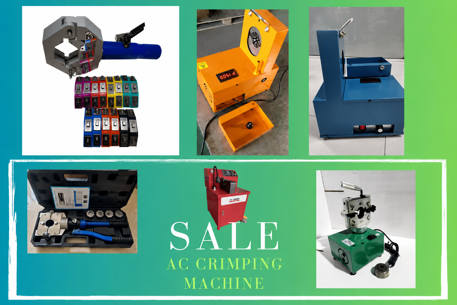
The machine provides the force. The dies determine the geometry. These are not the same function, and the dies are where most people underinvest.
A crimping machine without the correct die set is like a torque wrench with the wrong socket4. The tool works, but the result is wrong.
Equipment Checklist Before You Start
Here is what should be on your bench before any crimping job:
| Equipment | Purpose | Minimum Spec |
|---|---|---|
| Hydraulic or electric crimping machine | Applies uniform radial force | Matched to hose OD range |
| Die set (correct model for your fittings) | Shapes the crimp to spec | Manufacturer-matched to fitting series |
| Depth gauge or marker pen | Verifies insertion depth | Measurable to 1 mm |
| Vernier caliper | Measures post-crimp diameter | Resolution of 0.01 mm |
| Pressure tester | Confirms joint integrity | At least 500 psi capacity |
| Hose cutter | Produces a clean, square cut end | Rotary blade type preferred |
If any item on this list is missing or substituted with a workaround, the quality of the output cannot be guaranteed. This is not a preference — it is a process control requirement.
How Do You Choose the Correct Die?
This is the single most important decision in the entire process.
The correct die is determined by the fitting model and series, not by the hose outer diameter alone. Each fitting has a specified crimp diameter range. The die must match that range exactly. Using a die selected by eye or by hose OD only leads to dimensional errors that no operator technique can fix.
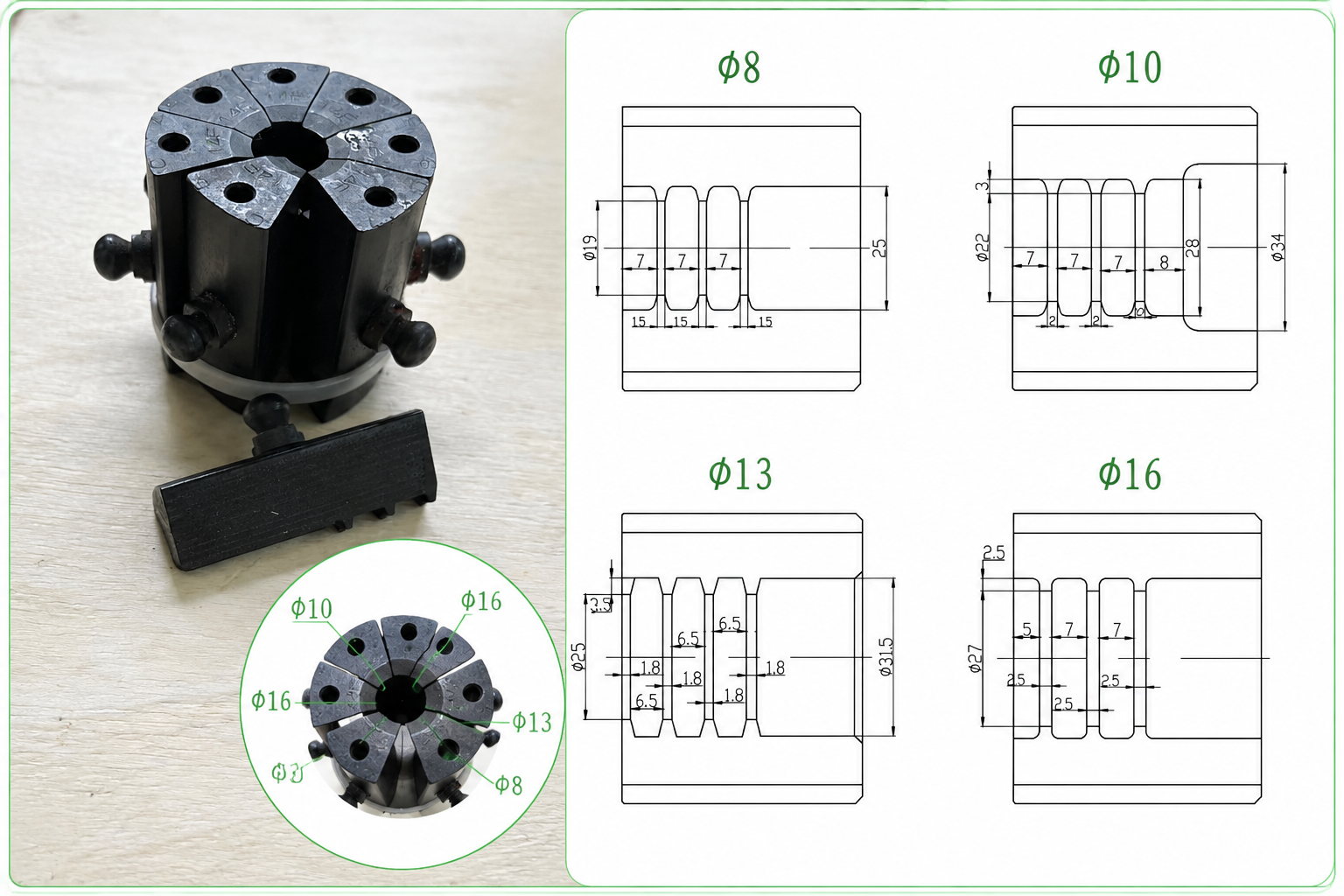
I see this mistake regularly. A technician has a hose that measures 16 mm OD. They grab the die labeled "16 mm" and crimp. The problem is that two different fitting series can use the same hose OD but require different crimp diameters5. The die label describes the hose, not the fitting geometry.
The right process is to identify the fitting model first, then look up the specified crimp diameter for that fitting in the manufacturer's die chart, then select the die that matches that diameter.
Why Mixed-Source Components Create This Problem
When dies come from one supplier, fittings from another, and the machine from a third, there is no guarantee that the die chart from supplier A was calibrated against the fitting dimensions from supplier B. Each manufacturer sets its own dimensional standards6.
This is the reason we supply machines, dies, fittings, and hose from the same factory. When all four components come from one production source, the die chart is built around the actual fitting dimensions we produce. There is no translation gap. The crimp diameter the die delivers matches the crimp diameter the fitting requires — because both numbers come from the same engineering baseline.
For distributors recommending tooling solutions to their workshop customers, this compatibility guarantee is a practical risk reduction. It is not about brand loyalty. It is about closing the dimensional gap that multi-supplier sourcing leaves open.
Die Selection Reference Logic
| What You Know | What You Need to Find | How to Find It |
|---|---|---|
| Hose OD | Fitting model | Check the system spec or the fitting packaging |
| Fitting model | Required crimp diameter | Look up the die chart for that fitting series |
| Required crimp diameter | Correct die | Match die spec to crimp diameter, not hose OD |
What Is the Step-by-Step Crimping Process?
Follow this sequence every time. Do not skip steps.
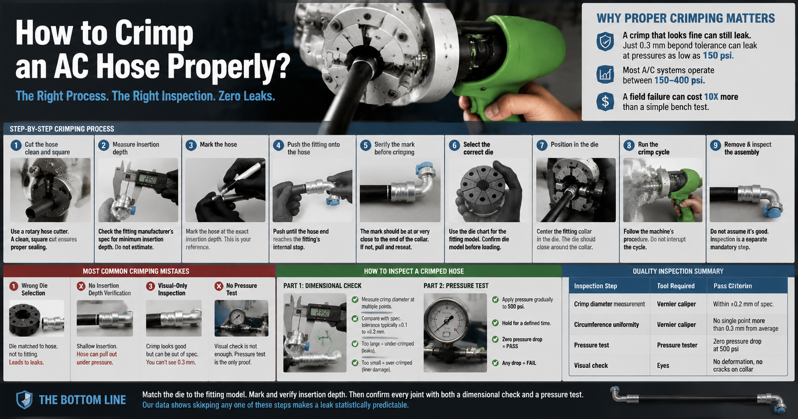
The correct crimping sequence is: cut the hose square, measure and mark insertion depth, push the fitting to the marked depth, verify the mark is still at the hose end, load the correct die, position the hose in the die, run the crimp cycle, and remove the assembly. Do not proceed to pressure testing until the dimensional check is done.
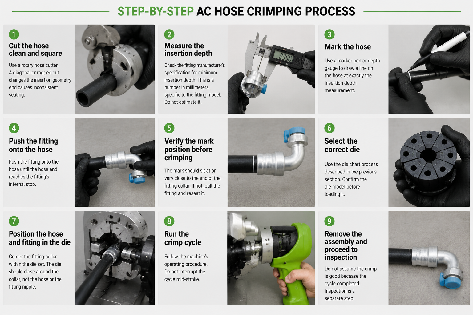
Here is each step in detail.
Step 1: Cut the hose clean and square. Use a rotary hose cutter. A diagonal or ragged cut changes the insertion geometry and causes inconsistent seating7.
Step 2: Measure the insertion depth for this fitting. Check the fitting manufacturer's specification for minimum insertion depth. This is a number in millimeters, specific to the fitting model. Do not estimate it.
Step 3: Mark the hose. Use a marker pen or depth gauge to draw a line on the hose at exactly the insertion depth measurement from Step 2. This line is your verification reference.
Step 4: Push the fitting onto the hose until the hose end reaches the fitting's internal stop. The mark from Step 3 should sit at or very close to the end of the fitting collar. If the mark has disappeared inside the fitting, the hose may have gone too deep. If the mark is far from the collar end, insertion is not complete.
Step 5: Verify the mark position before crimping. This is the checkpoint most technicians skip. Once the crimp happens, you cannot correct insertion depth. Check the mark. If it is not where it should be, pull the fitting and reseat it.
Step 6: Select the correct die. Use the die chart process described in the previous section. Confirm the die model before loading it into the machine.
Step 7: Position the hose and fitting in the die. Center the fitting collar within the die set. The die should close around the collar, not the hose or the fitting nipple.
Step 8: Run the crimp cycle. Follow the machine's operating procedure. Do not interrupt the cycle mid-stroke.
Step 9: Remove the assembly and proceed to inspection. Do not assume the crimp is good because the cycle completed. Inspection is a separate step.
What Are the Most Common Crimping Mistakes?
Most mistakes happen before the machine is turned on.
The most common crimping mistakes are: selecting a die by hose OD instead of fitting model, skipping the insertion depth mark, not verifying the mark before crimping, and passing a joint based on visual inspection alone without a pressure test.
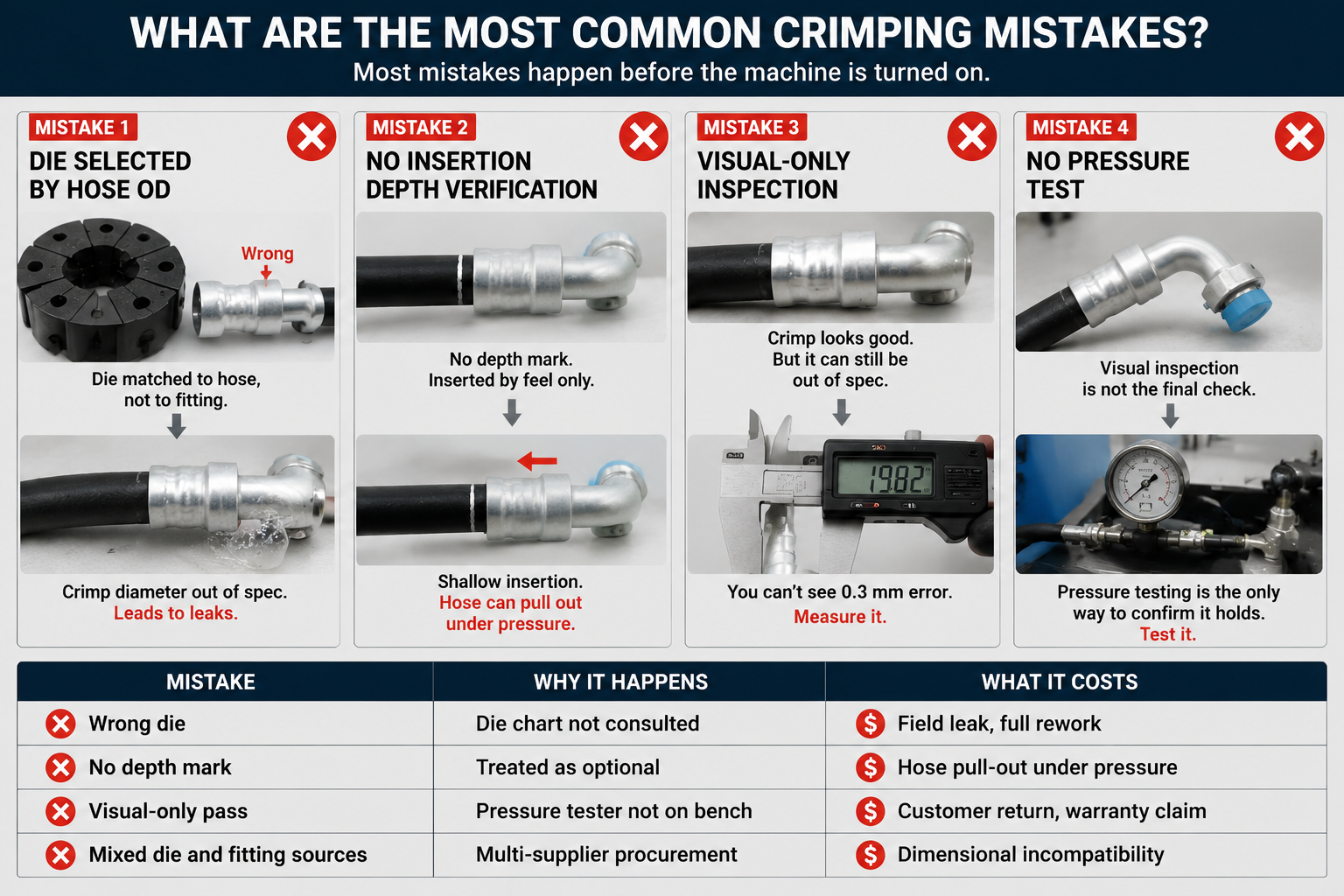
Let me go through each one.
Mistake 1: Die Selected by Hose OD
This is the highest-frequency error we see across all markets. The technician matches the die to the hose, not to the fitting. The crimp looks correct visually, but the diameter is off by 0.2 to 0.5 mm. That deviation is enough to cause leakage at normal operating pressure.
Mistake 2: No Insertion Depth Verification
Insertion depth is a discrete, measurable step. When technicians push the fitting onto the hose by feel and assume it is fully seated, they miss shallow insertions. A shallow insertion means the hose is not held at the designed engagement length. Under pressure, the hose backs out of the fitting8.
Mistake 3: Visual-Only Inspection
A crimp that looks uniform and clean can still be dimensionally out of spec. You cannot see a 0.3 mm diameter error with the naked eye. Without measuring the crimp diameter with a caliper, you do not know if the joint is within tolerance.
Mistake 4: No Pressure Test
Visual inspection is the first check. It is not the final check. Pressure testing is the only way to confirm the joint holds under the conditions it will face in a real system9.
| Mistake | Why It Happens | What It Costs |
|---|---|---|
| Wrong die | Die chart not consulted | Field leak, full rework |
| No depth mark | Treated as optional | Hose pull-out under pressure |
| Visual-only pass | Pressure tester not on bench | Customer return, warranty claim |
| Mixed die and fitting sources | Multi-supplier procurement | Dimensional incompatibility |
How Do You Inspect a Crimped Hose for Quality?
Inspection is a two-part process. Both parts are required.
Quality inspection for a crimped A/C hose has two steps: first, measure the crimp diameter with a vernier caliper and confirm it falls within the tolerance specified for that fitting model; second, run a pressure test to at least 500 psi and hold for a defined period with no pressure drop. Passing the first step does not replace the second.
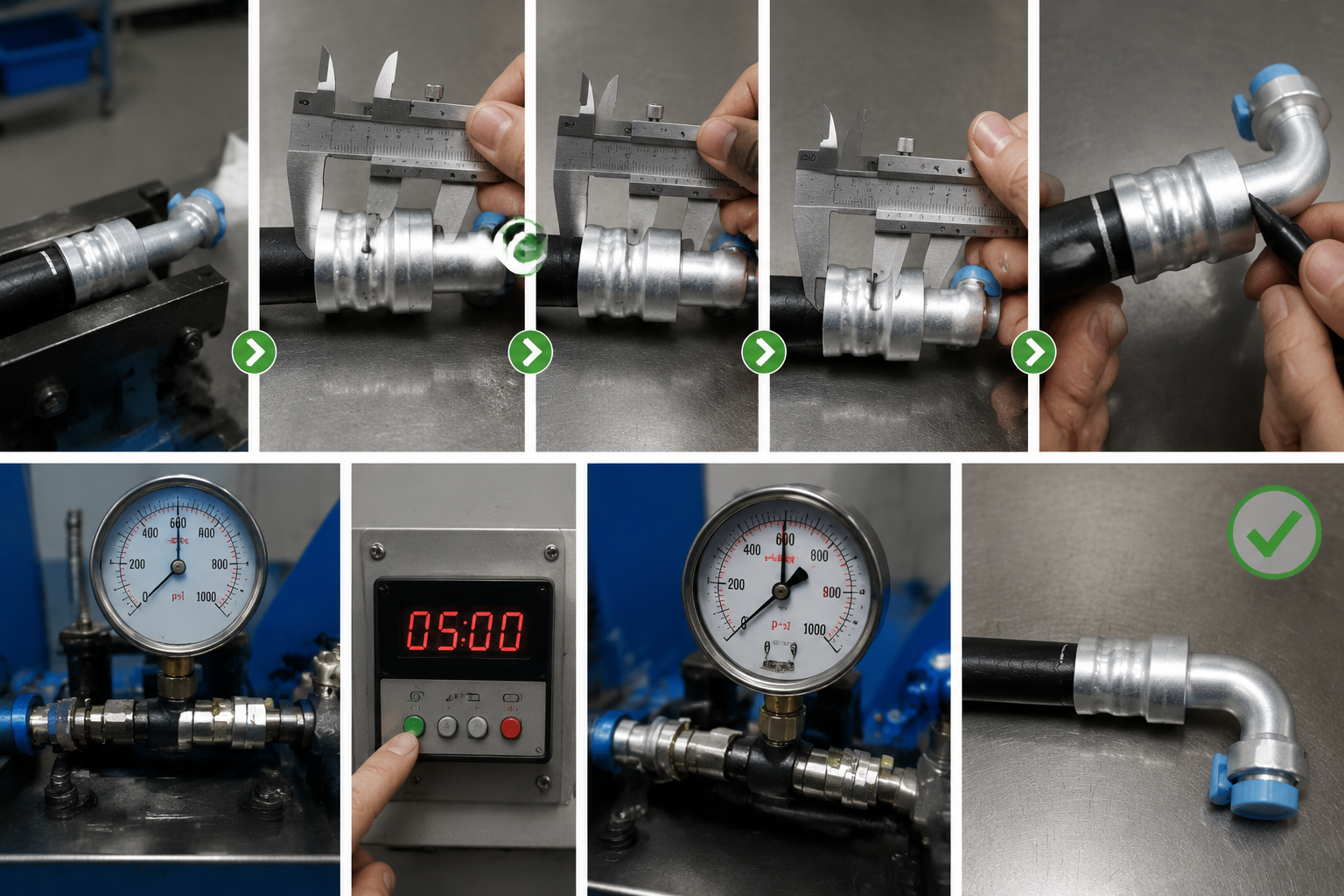
Part 1: Dimensional Check
Use a vernier caliper to measure the outer diameter of the crimped collar at multiple points around the circumference. Compare each measurement to the crimp diameter specification for that fitting model.
In our QC records, the acceptable tolerance is typically ±0.1 to ±0.2 mm depending on the fitting series10. Any reading outside that range means the crimp does not pass — even if it looks fine.
If the diameter is too large, the fitting is under-crimped and the seal is not compressed sufficiently. If the diameter is too small, the fitting may be over-crimped and the inner liner of the hose could be damaged11.
Part 2: Pressure Test
After the dimensional check passes, connect the assembly to a pressure tester. Apply pressure incrementally to the target test pressure — in our factory we test assembled hoses to 500 psi as a standard pre-shipment check12. Hold the pressure for a defined period and monitor for any drop.
A pressure drop means there is a leak somewhere in the assembly. Even a small, slow drop is a failure. Do not pass a joint that shows any pressure loss during the hold period.
| Inspection Step | Tool Required | Pass Criterion |
|---|---|---|
| Crimp diameter measurement | Vernier caliper | Within ±0.2 mm of spec (check fitting datasheet) |
| Circumference uniformity | Vernier caliper | No single point more than 0.3 mm from average |
| Pressure test | Pressure tester | Zero pressure drop at 500 psi over hold period |
| Visual check | Eyes | No visible deformation, no cracking on collar |
The visual check is still useful — it catches obvious deformation or cracking — but it is the last item on the list, not the only item.
Conclusion
Most A/C hose crimping failures are preventable. Match the die to the fitting model, mark and verify insertion depth, then confirm every joint with both a dimensional check and a pressure test. Our factory data shows that skipping any one of these steps makes a leak statistically predictable. Treat these as precision steps, not setup shortcuts, and your crimp quality will hold.
<!--[googlesitekit-end-of-content]-->
"[PDF] Introduction to Hydraulic Hose and Fittings", https://dlnr.hawaii.gov/mk/files/2017/01/Freitas-S-18-a.pdf. Engineering studies on hose-fitting crimp geometry establish that small dimensional deviations in crimp diameter can compromise the radial seal force sufficient to cause leakage at operating pressures; the specific threshold varies by fitting series and hose construction. Evidence role: mechanism; source type: paper. Supports: The relationship between crimp diameter deviation and pressure leak thresholds in hose fittings. Scope note: Published literature typically reports ranges across fitting types rather than a single deviation value, so direct numerical correspondence to the 0.3 mm figure cited here may not be available. ↩
"[PDF] R-1234yf A/C Update - Regulations.gov", https://downloads.regulations.gov/EPA-HQ-OAR-2014-0198-0244/attachment_15.pdf. SAE International and automotive HVAC technical references document typical operating pressures for vehicle A/C systems, with high-side pressures commonly ranging from approximately 150 to over 400 psi depending on refrigerant type, ambient temperature, and compressor load. Evidence role: statistic; source type: institution. Supports: Typical high-side and low-side operating pressure ranges for automotive air conditioning systems using common refrigerants. Scope note: Exact pressure ranges vary significantly by refrigerant type and operating conditions; the cited range represents a general envelope rather than a single authoritative figure. ↩
"Update on the Cost-Effectiveness of Inspection and Maintenance", https://nepis.epa.gov/Exe/ZyPURL.cgi?Dockey=9100UOFM.TXT. Quality management literature, including work derived from Juran and Feigenbaum's cost-of-quality frameworks, consistently documents that failure costs incurred after product delivery are an order of magnitude or more greater than prevention and appraisal costs applied during production. Evidence role: general_support; source type: research. Supports: That detecting and correcting defects in the field is substantially more expensive than catching them during assembly inspection. Scope note: Published cost ratios vary widely by industry and defect type; the specific 10x figure cited in the article reflects internal data and may not correspond directly to published benchmarks. ↩
"[PDF] Introduction to Hydraulic Hose and Fittings", https://dlnr.hawaii.gov/mk/files/2017/01/Freitas-S-18-a.pdf. Engineering references on metal forming and hose assembly describe the crimping die as the geometry-defining element of the assembly process; the machine provides hydraulic or mechanical force, but the final crimp diameter is controlled by the die's closed-position inner diameter, making die selection the primary determinant of dimensional outcome. Evidence role: mechanism; source type: education. Supports: That in hose crimping operations, the die geometry determines the final crimp diameter and profile, while the machine provides only the compressive force. Scope note: This principle is well-established in manufacturing engineering but is more commonly documented for general metal forming than specifically for refrigerant hose fitting applications. ↩
"[PDF] Introduction to Hydraulic Hose and Fittings", https://dlnr.hawaii.gov/mk/files/2017/01/Freitas-S-18-a.pdf. Fitting manufacturers' technical documentation and die selection charts commonly list multiple crimp diameter specifications for fittings sharing the same nominal hose size, reflecting differences in collar wall thickness, ferrule design, and sealing geometry across product series. Evidence role: case_reference; source type: institution. Supports: That multiple fitting series designed for the same nominal hose outer diameter can specify different crimp diameters, making hose OD an insufficient basis for die selection. Scope note: This is most clearly demonstrated by consulting specific manufacturer die charts, which are proprietary; published academic literature on this specific variation is limited. ↩
"AC Hose by the Foot or Spool | Barrier & Reduced-Barrier Hose", https://www.autocoolingsolutions.com/collections/bulk-ac-hose?srsltid=AfmBOooNuGeknXb1CF1Pyjj6wul0_kfh9XFfAD5cKKo7yuGG6D7r4Opw. While SAE and ISO publish baseline performance standards for refrigerant hose assemblies, individual fitting manufacturers maintain proprietary crimp diameter specifications tied to their specific fitting geometry; these specifications are not always interchangeable across brands even when nominal hose sizes match. Evidence role: historical_context; source type: institution. Supports: That hose fitting manufacturers maintain proprietary dimensional specifications that are not universally standardized, creating compatibility risks when mixing components from different suppliers. Scope note: This claim is well-supported by industry practice but is rarely documented explicitly in published standards, which tend to specify performance outcomes rather than prescribing dimensional interchangeability between manufacturers. ↩
"[PDF] Introduction to Hydraulic Hose and Fittings", https://dlnr.hawaii.gov/mk/files/2017/01/Freitas-S-18-a.pdf. Industry assembly standards for hydraulic and refrigerant hose, including guidance published by SAE and hose manufacturers' technical bulletins, specify that hose ends must be cut square and clean to ensure uniform insertion depth and consistent radial contact between hose and fitting. Evidence role: mechanism; source type: institution. Supports: That hose end cut quality, specifically squareness, affects fitting insertion depth consistency and assembly integrity. Scope note: Specific standards vary by hose type and application; the mechanical consequence of a non-square cut is well-established in principle but quantified failure data for this specific cause is limited in open literature. ↩
"[PDF] Introduction to Hydraulic Hose and Fittings", https://dlnr.hawaii.gov/mk/files/2017/01/Freitas-S-18-a.pdf. Studies on hose-fitting assembly mechanics demonstrate that axial pull-out resistance is directly related to the length of hose engaged within the fitting collar; assemblies with insertion depths below the specified minimum exhibit reduced retention force and are prone to hose separation under sustained or cyclic pressure loading. Evidence role: mechanism; source type: paper. Supports: That insufficient hose insertion depth into a fitting reduces the axial retention force, making the assembly susceptible to hose pull-out under internal pressure. Scope note: Published pull-out force data is more extensively documented for hydraulic hose than for refrigerant A/C hose specifically; the mechanical principle is transferable but quantitative thresholds differ by application. ↩
"[PDF] pressure and leak testing - Industrial Refrigeration Consortium", https://irc.wisc.edu/export.php?ID=263. Quality assurance standards for fluid power and refrigerant hose assemblies, including SAE J1273 and related guidance documents, specify proof pressure testing as a required verification step for hose assemblies, recognizing that dimensional and visual checks cannot detect all leak paths that manifest only under pressurized conditions. Evidence role: expert_consensus; source type: institution. Supports: That pressure testing is the required and definitive method for verifying hose assembly joint integrity, and that visual inspection alone is insufficient. Scope note: SAE J1273 addresses hydraulic hose assemblies; equivalent refrigerant-specific standards should be consulted for A/C applications, and the specific hold time and acceptance criteria vary by standard and application. ↩
"[PDF] Introduction to Hydraulic Hose and Fittings", https://dlnr.hawaii.gov/mk/files/2017/01/Freitas-S-18-a.pdf. Fitting manufacturers' technical datasheets and industry standards bodies such as SAE specify crimp diameter tolerances for refrigerant hose assemblies; published values typically fall within a range of ±0.1 to ±0.3 mm depending on fitting series and hose construction. Evidence role: definition; source type: institution. Supports: That crimp diameter tolerances for refrigerant hose fittings fall within a range of approximately ±0.1 to ±0.2 mm. Scope note: Tolerances are fitting-series-specific and not uniform across manufacturers; the range cited in the article reflects one manufacturer's internal standard and may differ from other published specifications. ↩
"[PDF] Introduction to Hydraulic Hose and Fittings", https://dlnr.hawaii.gov/mk/files/2017/01/Freitas-S-18-a.pdf. Technical literature on hose assembly mechanics describes over-crimping as a condition in which excessive radial compressive force deforms the hose inner tube or liner beyond its elastic limit, potentially creating flow restrictions, liner cracking, or reduced burst pressure capacity. Evidence role: mechanism; source type: paper. Supports: That excessive crimp compression can deform or damage the inner liner of a hose, compromising its pressure-holding integrity. Scope note: Published studies on this failure mode are more common for hydraulic hose than for refrigerant-specific A/C hose; the underlying mechanical principle is transferable but direct refrigerant hose data may be limited. ↩
"Federal Motor Vehicle Safety Standards; Brake Hoses", https://www.federalregister.gov/documents/2003/05/15/03-11292/federal-motor-vehicle-safety-standards-brake-hoses. SAE J2064, which governs barrier hose for use with refrigerants in automotive air conditioning systems, specifies proof pressure and burst pressure requirements for hose assemblies; proof pressure requirements are typically set at a multiple of the maximum working pressure to verify assembly integrity before installation. Evidence role: general_support; source type: institution. Supports: That a proof pressure test of approximately 500 psi is consistent with industry standards for refrigerant hose assembly quality verification. Scope note: The specific test pressure required depends on hose type, refrigerant, and applicable standard; 500 psi may exceed or fall short of the required proof pressure for specific configurations. ↩