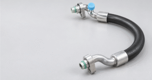
Sourcing a replacement automotive AC hose fitting sounds straightforward — until you realize you don't know exactly what you have. Buyers who need a custom AC fitting often lose weeks in back-and-forth with manufacturers, not because the part is rare, but because the wrong information arrived first. Measuring an AC fitting correctly before you contact a supplier is the single most valuable thing you can do.
Measuring an AC fitting correctly requires four pieces of information: the thread outer diameter, the thread pitch, the hose connection end inner diameter, and the connection interface type (O-ring, flare, or block). With those four dimensions plus clear photos of all three ends, any competent manufacturer can assess whether a fitting is reproducible and quote production on the first contact — without multiple rounds of clarification.
The sections below walk through each measurement step-by-step. More importantly, they explain why each measurement matters to a reproduction decision — so you understand what to capture before you send anything to a supplier.
Why Accurate AC Fitting Measurements Matter?
Most procurement delays aren't caused by tooling problems or production capacity. They're caused by incomplete specs arriving at the factory. When our technical team receives a fitting inquiry, the most common reason a quote gets delayed is a missing thread pitch or an unlabeled hose end.
Accurate measurements matter because a manufacturer cannot begin a production assessment without confirmed thread standard, hose compatibility, and sealing interface. An underspecified fitting creates a chain of clarification rounds that adds days or weeks to your timeline. A fully measured fitting can be quoted — and often sampled — within days.
The financial risk is real. If a manufacturer produces a batch based on assumed dimensions, the parts may not seal correctly, mate with the mating connector, or crimp securely onto the hose. The cost of one rework cycle — reshipping samples, waiting for correction, re-approving — typically exceeds the cost of spending twenty minutes measuring accurately before the first inquiry.
Think of fitting measurement as the entrance fee for a fast, accurate quote. Skip it, and you're paying in time instead.
What Tools Do You Need to Measure an AC Fitting?
You don't need a metrology lab. Most importers and distributors can get usable measurements with basic workshop tools. The problem is usually skipping the thread pitch gauge — and that's where misidentification happens.
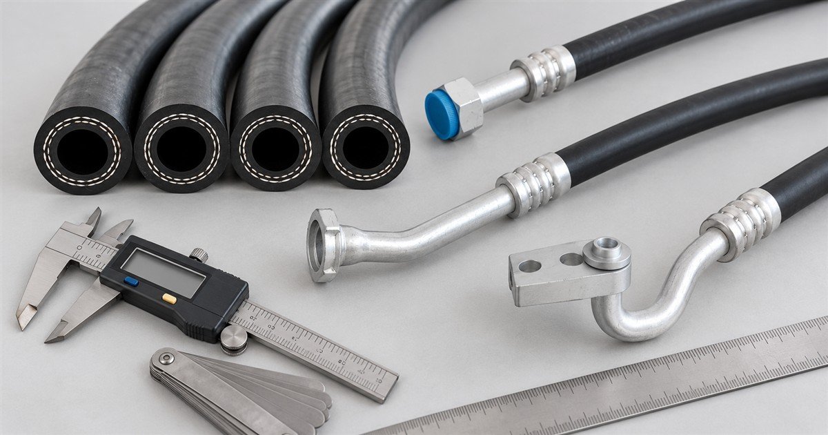
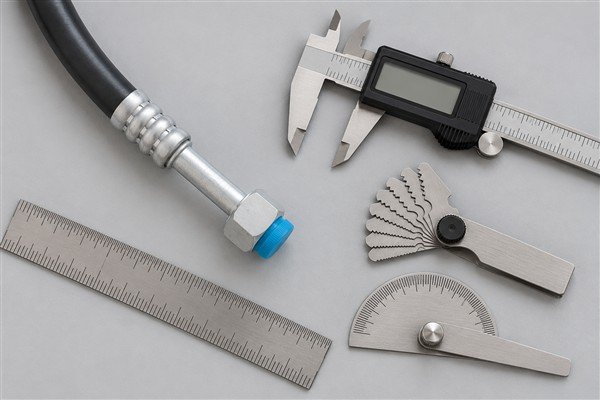
To measure an AC fitting accurately, you need: a digital vernier caliper (for OD, ID, and length), a thread pitch gauge (to identify coarse vs. fine pitch and confirm SAE vs. Metric), and a flat reference surface for measuring overall length. A ruler or measuring tape can supplement these for overall length checks.
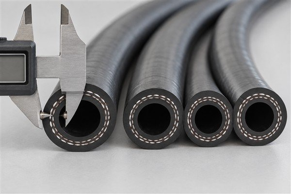
Here's a practical breakdown:
- Digital vernier caliper: Essential. Measures thread OD, hose connection OD and ID, and overall length. Accuracy to 0.02 mm is sufficient for fitting reproduction1.
- Thread pitch gauge: Often overlooked, always critical. This is a set of metal blades, each stamped with a different pitch value. You test blades against the thread until one sits flush with no gaps.
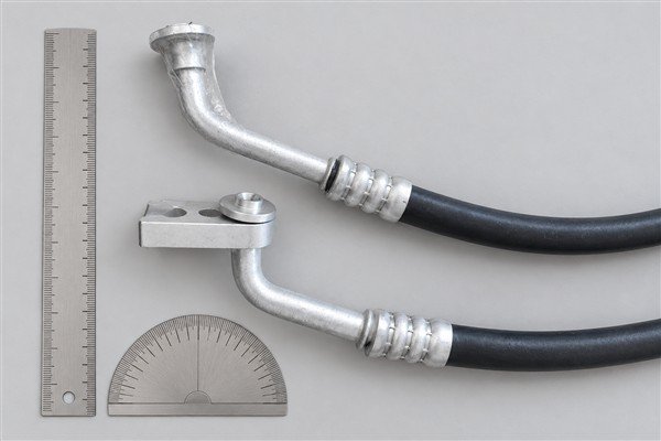
- Angle reference card or protractor: For confirming 45° or 90° bends. Most buyers visually estimate this — which is acceptable as a starting point, but a reference confirms it.
- Camera with a close-up mode: Not a measuring tool, but essential for your inquiry submission.
If you don't have a thread pitch gauge, a machinist's ruler can give you a rough pitch count — count the number of thread crests across 10 mm and divide. But this is a fallback, not a method. Get a pitch gauge if you're sourcing fittings regularly.
How to Measure the Hose Connection End?
The hose connection end is where the fitting crimps onto the refrigerant hose. If this end is misspecified, the fitting won't hold pressure — regardless of how accurate the thread measurements are.
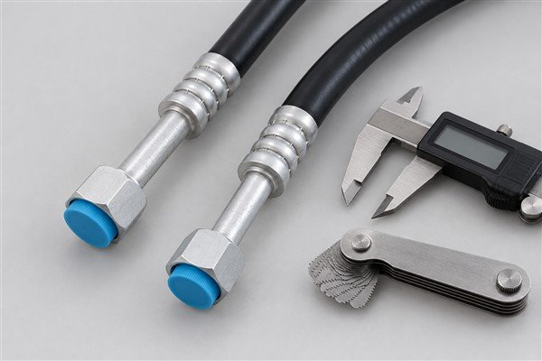
Measure the hose connection end by recording two values: the inner diameter (ID) of the hose socket opening, and the outer diameter (OD) of the barb or tail. These two values, combined with the hose wall thickness, determine crimp die compatibility and confirm whether the fitting mates with the intended hose series.
What the ID tells a manufacturer
The hose ID tells the manufacturer which hose bore the fitting is designed for — typically #6, #8, #10, or #12 in SAE sizing. A #8 hose, for example, For automotive A/C hoses, a common #8 size has a nominal inside diameter of 13/32 inch (approximately 10.3 mm). Always confirm the actual inside and outside diameters against the hose manufacturer’s specifications before selecting a fitting.2. The fitting tail OD must correspond to the hose ID with a controlled interference fit.
What the OD tells a manufacturer
The tail OD determines crimp die selection. If your OD is off by even 0.5 mm, the crimped connection may under-compress or over-compress the ferrule, causing leaks or hose damage under pressure cycling3.
How to measure it
- Use your caliper's inside jaw to measure the socket opening ID.
- Use the outside jaw to measure the largest barb OD.
- Note whether the tail is smooth, barbed (single or double), or flared — this affects how the hose seals.
- Measure the insertion depth of the tail (how far it enters the hose). This determines ferrule length.
Record all four values. Don't estimate from a visual comparison to another fitting you have on the shelf — two fittings can look identical and differ by 1 mm in tail OD.
How to Measure Thread Diameter?
Thread diameter is the most visible dimension — and therefore the one buyers most often think they've captured when they haven't captured what actually matters4.
Measure thread outer diameter (OD) with a digital caliper across the thread crests at the widest point. For a straight thread, this is straightforward. For a tapered thread, measure at the first full thread near the shoulder. Record the value in millimeters, not as a size designation, to avoid conversion errors.
Common AC fitting thread ODs include 12 mm, 14 mm, 16 mm, and 18 mm in metric, and 9/16", 3/4", and 7/8" in SAE. But a 14 mm OD alone does not identify the thread — you still need the pitch.
Why diameter alone isn't enough
Two fittings with the same 14 mm OD can have completely different threads:
- M14 × 1.5 (Metric, 1.5 mm pitch)
- M14 × 1.0 (Metric, 1.0 mm pitch)
These will not interchange. And neither will thread with a 9/16"-18 UNF thread, which has a different diameter and pitch system entirely. This is why measuring OD without measuring pitch is an incomplete specification.
How to Identify Thread Type and Connection Style?
This is the section most buyers need most — and most often skip. Thread type misidentification is the single most common source of rework in custom fitting reproduction.
Identify thread type by combining two measurements: thread OD (from your caliper) and thread pitch (from your thread pitch gauge or manual count). SAE and Metric threads both use a 60° flank angle, so they cannot be distinguished by appearance alone5. Only pitch measurement separates them reliably.
SAE vs. Metric: the practical difference
| Parameter | SAE (UNF/UNC) | Metric (M series) |
|---|---|---|
| Thread angle | 60° | 60° |
| Pitch unit | Threads per inch (TPI) | mm between crests |
| Common AC sizes | 7/16"-20, 1/2"-20, 5/8"-18 | M12×1.5, M14×1.5, M16×1.5 |
| Identification method | TPI count + diameter | Pitch (mm) + diameter (mm) |
When our team receives a photo of an unlabeled fitting, we look at pitch density as a first filter. A coarser pitch pattern suggests a lower TPI or higher mm pitch. But we always confirm with the buyer's measured values — visual estimation from a photo is a starting point, not a specification.
Connection interface: O-ring, flare, or block?
Beyond the thread, the connection interface determines how the fitting seals against its mating part:
- O-ring face seal (ORFS): A machined flat face with an O-ring groove. Common on high-pressure lines.
- Flare (45° or 37°): The sealing surface is a cone-to-cone contact. No O-ring. Common on older or simpler systems.
- Block fitting: A flat-face fitting that bolts directly to a component block. Uses a gasket or O-ring. Common at compressor and condenser connections.
Photograph the face of the thread end straight-on. The interface type is usually visible — a groove indicates ORFS, a machined cone indicates flare, a flat face with bolt holes indicates block.
How to Measure Straight, 45° and 90° Fittings?
Angle matters because it affects routing. A 90° fitting used where a 45° fitting belongs creates hose tension, vibration fatigue, and premature failure6.
Measure the fitting angle by placing the fitting on a flat surface and using a protractor or angle reference card against the bend. Straight (0°), 45°, and 90° are the three standard configurations. Most buyers can visually confirm the angle — but photograph the side profile against a flat reference for the manufacturer's verification.
For measurement purposes:
- Straight fittings: No angle to measure. Measure overall length from thread shoulder to hose tail end.
- 45° fittings: Place on a flat surface, measure the angle of the hose tail relative to the thread axis. Confirm the bend radius if space constraints are tight.
- 90° fittings: The thread axis and hose axis should be perpendicular. Measure the two arm lengths independently — thread end to center of bend, and bend center to hose end.
A side-profile photograph with a ruler in frame is the clearest way to communicate this to a manufacturer without ambiguity.
How to Measure the Overall Length of an AC Fitting?
Overall length is a secondary specification for most reproduction jobs — but it matters when the fitting must route through a tight engine bay or mate with a specific bracket or block position.
Measure overall length from the outermost point of the thread end (not including thread lead-in) to the end of the hose tail. For angled fittings, measure each arm independently. Record in millimeters. A tolerance of ±1–2 mm is typically acceptable for replacement production unless the original design has a strict envelope constraint7.
Place the fitting on a flat surface and use your caliper extended fully, or a precision ruler. For 90° fittings, record both:
- Thread arm length (thread face to bend center)
- Hose arm length (bend center to hose tail end)
This gives the manufacturer everything needed to confirm the fitting will fit the intended routing without modification.
How to Identify an AC Fitting When You Don't Know the Part Number?
Part numbers get discontinued. Labels wear off. Fittings get sourced from secondary markets with no documentation. This is one of the most common situations buyers come to us with — a worn fitting and no reference.
To identify an AC fitting without a part number, systematically measure thread OD, thread pitch, hose connection ID, and connection interface type. Cross-reference the thread OD and pitch against SAE and Metric thread tables. If you cannot confirm the thread standard from measurements alone, send the original sample to a manufacturer for physical evaluation.
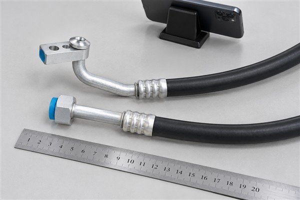
Here's the identification workflow I'd recommend:
- Clean the fitting. Remove grease and debris. Thread detail and interface type must be visible.
- Photograph first — three angles (thread face straight-on, hose end from side, full-length side profile).
- Measure thread OD with your caliper.
- Measure thread pitch with your thread pitch gauge. If you're between two blades, record both and flag it.
- Measure hose connection ID and OD.
- Identify the interface type (ORFS, flare, or block) from the thread face photo.
- Record the angle (0°/45°/90°) and overall length.
- Send everything to your manufacturer as a single inquiry: 3 photos + 6 measured values + the original fitting if possible.
If the original fitting is in two pieces from a failure, send both pieces. A broken fitting with measurements is far more useful than a vague description of an intact one.
What Photos and Measurements Should You Send a Manufacturer?
When buyers ask what to send us for a custom fitting inquiry, I give them the same list every time. A complete submission gets a production assessment within one business day. An incomplete one starts a clarification cycle.
Send three photos (thread end straight-on, hose end from the side, full-length side profile with a ruler in frame) plus six measured values: thread OD, thread pitch, hose connection ID, hose connection OD, connection interface type, and fitting angle. Include overall length and any system pressure or refrigerant type if known.
The complete inquiry checklist
Photos:
- [ ] Thread face, straight-on (shows interface type and thread profile)
- [ ] Hose connection end, side view (shows tail OD, barb count, and length)
- [ ] Full-length side profile with ruler in frame (shows angle and overall length)
Measurements:
- [ ] Thread OD (mm)
- [ ] Thread pitch (mm or TPI)
- [ ] Hose connection ID (mm)
- [ ] Hose tail OD (mm)
- [ ] Connection interface (ORFS / flare / block — or photo of thread face if unsure)
- [ ] Fitting angle (0° / 45° / 90°)
- [ ] Overall length (mm)
Optional but helpful:
- [ ] Refrigerant type (R134a, R1234yf, R22, etc.)
- [ ] System working pressure
- [ ] Target quantity for production
- [ ] Original sample (physical, by courier)
Can an AC Fitting Be Reproduced from an Original Sample?
This is the question buyers ask most often when they have a broken or discontinued fitting with no documentation at all.
Yes — an original sample is the most reliable basis for fitting reproduction. When our technical team receives a physical sample, we can confirm thread standard, pitch, interface type, and hose compatibility directly from the part. This eliminates ambiguity and allows us to produce a matched reproduction without relying on the buyer's measurement accuracy.
A physical sample is particularly valuable when:
- The thread is worn or partially damaged (we can still gauge the pitch from intact crests)
- The buyer is unsure of the connection interface type
- The fitting has a non-standard combination of dimensions
When buyers ship us an original fitting, our team documents all critical dimensions, photographs the key surfaces, and returns the sample with the production proposal. We don't require the buyer to have measured anything — though having partial measurements speeds the process.
The only limitation is condition. A fitting that is sheared, melted, or corroded beyond readable thread crests may not be reproducible from sample alone. In those cases, a combination of partial sample data plus matching against our standard range often resolves it.
Frequently Asked Questions
How do I identify an unknown AC fitting?
Measure thread OD and pitch with a caliper and thread pitch gauge, then identify the hose connection end ID and OD. Photograph the thread face to identify the sealing interface (O-ring groove, flare cone, or flat block face). Cross-reference against SAE and Metric thread tables, then send all measurements and photos to a manufacturer for confirmation.
How do I measure an AC fitting thread?
Use a digital caliper to measure thread outer diameter across the crests. Then use a thread pitch gauge to identify the pitch — the blade that sits flush against the thread with no gaps is your pitch value. Record OD in mm and pitch in mm or TPI. Do not rely on diameter alone — two fittings with identical OD can have different pitches and will not interchange.
Can I identify a fitting from a photo?
A photo is a useful starting point but not a complete specification. Photos can reveal connection interface type, approximate angle, and visible thread profile. They cannot confirm thread OD, thread pitch, or hose end dimensions — all of which require physical measurement. A photo combined with measured values is a workable inquiry; a photo alone is not.
Can a manufacturer copy an original AC fitting?
Yes, in most cases. A physical sample allows a manufacturer's technical team to measure and confirm all critical dimensions directly. This is the most reliable method when part numbers are unavailable or documentation is missing. The fitting should be clean and have at
<!--[googlesitekit-end-of-content]-->
"Engineering fit", https://en.wikipedia.org/wiki/Engineering_fit. SAE and ISO standards for automotive hydraulic and refrigerant fittings specify tolerances typically in the 0.05-0.2mm range for critical sealing surfaces, making 0.02mm measurement resolution adequate for specification purposes. Evidence role: general_support; source type: institution. Supports: that sub-0.1mm measurement accuracy meets typical automotive fitting tolerances. ↩
Automotive A/C hose size labels should not be interpreted using the hydraulic hose dash-size rule of 1/16-inch increments. A common #8 automotive A/C hose has a nominal inside diameter of 13/32 inch (approximately 10.3 mm). Actual dimensions may vary by hose series and manufacturer; confirm the hose’s inside and outside diameters using the manufacturer’s dimensional table before selecting fittings or ferrules. ↩
"Car Air Conditioner - How Does It Work? (3D Animation) - YouTube", https://www.youtube.com/watch?v=YII_LE2IDmA. Automotive air conditioning systems undergo pressure cycling between low-side pressures of 20-40 psi and high-side pressures of 200-350 psi as the compressor cycles on and off in response to thermal load, creating repetitive stress on hose connections and sealing surfaces. Evidence role: mechanism; source type: education. Supports: that automotive AC systems experience cyclical pressure variation during compressor operation. ↩
"Pitch Diameter : Ensuring Perfect Fastener Fit and ...", https://www.bcepi.com/fasteners-101/pitch-diameter-in-thread-design-ensuring-perfect-fastener-fit. Quality engineering studies of fastener and fitting procurement identify incomplete thread specification—particularly omission of pitch data—as among the most frequent causes of part mismatch and assembly rejection. Evidence role: general_support; source type: research. Supports: that incomplete thread specifications are a common source of procurement and assembly errors. Scope note: This pattern is documented in industrial quality literature generally, though specific to threaded components rather than AC fittings exclusively. ↩
"ISO metric screw thread - Wikipedia", https://en.wikipedia.org/wiki/ISO_metric_screw_thread. Both ISO 68-1 (metric threads) and ASME B1.1 (unified inch threads) specify a 60° included thread angle, making the thread profiles geometrically similar and visually indistinguishable without pitch measurement. Evidence role: mechanism; source type: institution. Supports: that both ISO metric and unified inch thread systems specify 60° thread angles. ↩
"Hydraulic Hose Routing & Support | Prevent Premature Failures", https://acehoses.com.au/hydraulic-hose-routing-support/. Hydraulic system design research demonstrates that hose installations with improper bend radii or angular misalignment experience concentrated flexural stress and amplified vibration transmission, reducing fatigue life by 40-70% compared to properly routed assemblies. Evidence role: mechanism; source type: research. Supports: that improper hose routing and fitting angles accelerate fatigue failure through stress concentration and vibration. Scope note: These failure acceleration rates are documented for hydraulic hoses generally; specific AC refrigerant hose performance may vary based on construction and pressure cycling. ↩
"Standard Tolerances in Manufacturing: ISO 2768 & ISO 286 | Xometry Pro", https://xometry.pro/en/articles/standard-tolerances-manufacturing/. Aftermarket automotive component standards generally permit dimensional variations of 1-3mm in non-critical dimensions (those not affecting sealing or thread engagement) when the replacement part maintains functional compatibility with the original routing and connection points. Evidence role: general_support; source type: institution. Supports: that aftermarket replacement fittings allow for modest dimensional variation when function is preserved. Scope note: This applies to overall length and envelope dimensions; sealing surfaces and thread dimensions require tighter tolerances as specified in connection standards. ↩